




 " />
" />【 WeChat QR code consultation 】
+86 13698775878
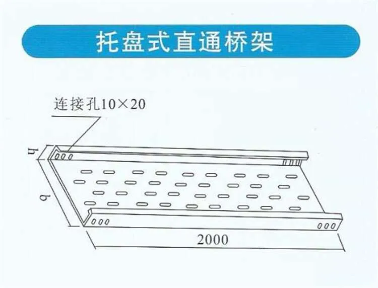
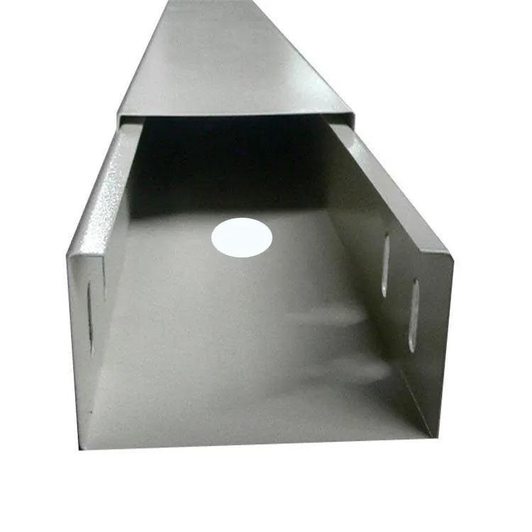
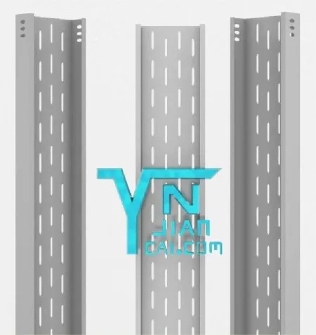
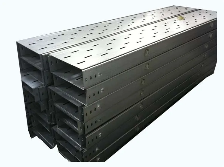
The surface treatment of tray type cable tray is divided into galvanizing and painting. In heavy corrosion environments, special anti-corrosion treatment can be applied.
Tray type cable tray is equipped with protective covers. If protective covers are needed, they can be noted when ordering or ordered according to the protective cover model. All its accessories are interchangeable with ladder type and trough type cable trays.
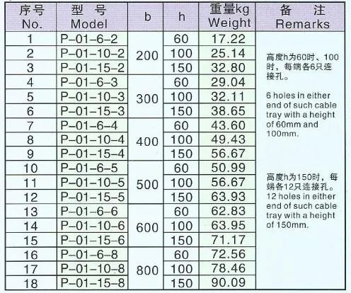
Maximum allowable uniform load and variables of tray type cable tray under different spans.
Cable tray (cable bracket) is the general term for a rigid structural system with closely supported cables, composed of straight sections, bends, components of trays or ladders, as well as support arms (arm type brackets), hangers, etc.
1. When cable trays, trunking and their supports and hangers are used in corrosive environments, they should be made of corrosion-resistant rigid materials, or anti-corrosion treatment should be applied. The anti-corrosion treatment method should meet the requirements of engineering environment and durability.
2. In sections with fire protection requirements, cable trays can add boards, nets and other materials with fire-resistant or flame-retardant properties in cable ladders and trays to form closed or semi-closed structures, and take measures such as painting fire-resistant coatings on the surface of the tray and its supports and hangers. Its overall fire resistance should meet the requirements of relevant national specifications or standards.
3. In places with high engineering fire protection requirements, aluminum alloy cable trays should not be used.
4. The selection of width and height of cable ladders and trays should meet the requirements of filling rate. Generally, the filling rate in cable ladders and trays can be 40%~50% for power cables, 50%~70% for control cables, and 10%~25% engineering development margin should be reserved.
5. When selecting the load grade of cable tray, the working uniform load of cable tray should not be greater than the rated uniform load of the selected cable tray load grade. If the actual span of the cable tray supports and hangers is not equal to 2m, the working uniform load should meet the requirements.
6. Under the condition of meeting the corresponding load, the specifications and dimensions of various components and supports and hangers should match the straight sections and bend series of trays and ladders.
7. When selecting bends or lead-up and lead-down devices of cable tray, they should not be less than the minimum allowable bending radius of cables in the cable tray.
8. For steel cable trays with span greater than 6m and aluminum alloy cable trays with span greater than 2m or load bearing requirements greater than load grade D, strength, stiffness and stability calculation or test verification should be carried out according to engineering conditions.
9. When several groups of cable trays are laid in parallel at the same height, maintenance and inspection distances should be considered between adjacent cable trays.
10. Common specifications and dimensions of width and height of steel trays and ladders refer to Article 2.2.2 of CESC31:91 "Code for Design of Steel Cable Tray Engineering".
11. Common specifications and dimensions of width and height of aluminum alloy trays and ladders refer to Article 3.1.2 of CECS106:2000 "Technical Specification for Aluminum Alloy Cable Trays".
12. The standard length of straight single pieces of steel trays, ladders and aluminum alloy trays, ladders can be 2, 3, 4, 6m.
13. Surface anti-corrosion treatment methods of steel cable trays refer to Article 3.4.2 of CECS31:91 "Code for Design of Steel Cable Tray Engineering".
14. Surface anti-corrosion treatment methods of aluminum alloy cable trays see Table Article 4.4.1 of CECS 106:2000 "Technical Specification for Aluminum Alloy Cable Trays".
Construction and installation points
① The laying direction of cable trays and trunking should be short and direct, and should be laid along walls, columns or beams as much as possible.
② According to the laying direction of cable trays and trunking, propose to the civil engineering specialty and structural specialty the position and load of pre-embedded steel plates required for reserved wall holes, floor holes and hanger installation. And it should be coordinated with the technology specialty, plumbing specialty and power specialty.
③ For concealed metal trunking wiring in the ground, close cooperation with the civil engineering specialty is required during design, so as to reasonably determine the line path and equipment selection according to different structural types and building layouts.
④ Cables of different voltages and different uses should not be laid in the same layer of cable tray:
5. When installation or maintenance under engineering conditions does not need to consider additional concentrated loads, the working uniform load of cable ladders and trays is calculated according to the uniform distribution of cable self-weight.
6. Cable trays should not be laid in parallel with the following pipes. When unavoidable, the position of the cable tray should meet the following regulations, or corresponding protective measures should be taken.
(1. Cable trays should be above pipes with corrosive liquids.
(2. Cable trays should be below thermal pipes.
(3. When flammable and explosive gases are heavier than air, cable trays should be above the pipes.
(4. When flammable and explosive gases are lighter than air, cable trays should be below the pipes.
7. The minimum distance between cable trays and pipes see relevant standards.
8. Necessary spacing should be maintained between generic cabling cables and electrical equipment such as motors and power transformers nearby that may generate high-level electromagnetic interference. The spacing between generic cabling cables and power cables should comply with the provisions of Article 11.0.2 of GB/T 50311-2000 specification.
9. The spacing between generic cabling cables, optical cables and pipelines laid on walls and other pipelines should comply with the provisions of Article 11.0.2 of GB/T 50311-2000 specification.
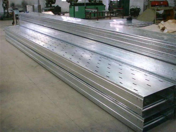
10. When cable trays are laid horizontally, the best span should be selected according to the load curve for support, and the span is generally 1.5~3.0m. When laid vertically, its fixed spacing should not be greater than 2m. 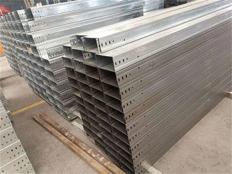
Scan code consultation



 English